Friday 26 June 2020

VW Heater/Blower installation

I've already overhalued the Polo heater giving it a thorough clean, new O-rings and new matrix so all should be good to go.

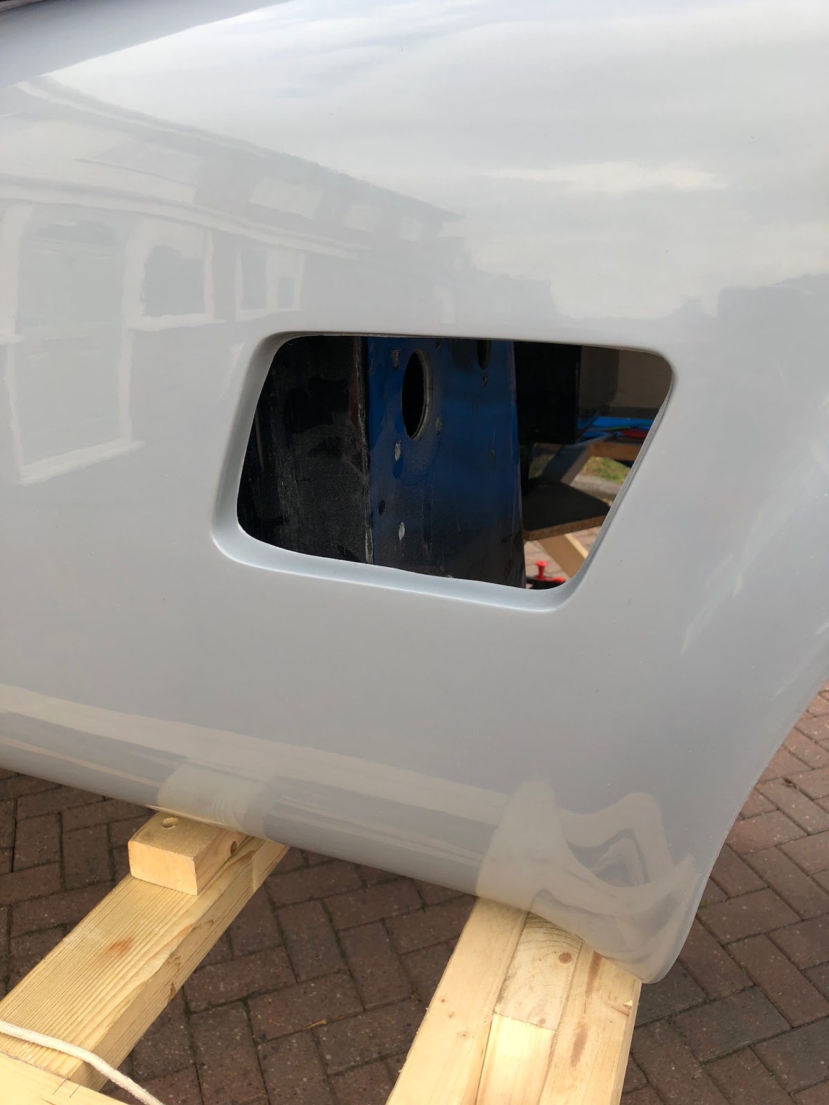
I've now cut the hole in the front bulkhead and carefully positioned the heater where I want it to fit.

I wanted the heater to be relatively easy to remove should the need arise further down the line if there are any issues with matrix etc. so spent quite a lot of time thinking how best to fix and seal to the front bulkhead.

I decided to make up a set of four stainless steel brackets to securely hold it in place and very quickly realised that access to both sides for the fixings was really difficult so opted for several bonded plates with rivnuts in. It took a little while using the tried and tested CAD (cardboard aided design 😊) but eventually  all fitted as I hooped. The two lower brackets will be isolated with a foam rubber strip.


The heater box will be sealed to the bulkhead to ensure that no water can get in from the engine bay.

Another thing I wanted to do was to tidy up how the heater hoses connect to the heater unit so I decided to set about making a cover for the heater with the hose connector mounts already in place. Not exactly straight forward but should work well and also look much cleaner when sprayed with body colour.

The top brackets are riveted to the top of the heater box above the matrix.


The heater was carefully taped in position so that the bracket holes could be marked and then drilled.


I made several plates with rivnuts in so that I could access the screws from the engine bay. These plates were then all bonded to the firewall and tunnel top.


Heater fully bolted in place. It will be sealed later when I've finished all the engine bay fitting out.


Side Louvres

I wanted to fit the side louvres from the outside securely with just a few screws. I've opted to go with a slightly different set from Andrzej on the Cobra Clum forum.

Therefore I have removed the inner wall that runs around the louvre apperture but was a little concerned about strength so opted to bond some aluminium angle both above and below each louvre and then screw the louvres to these.

Before
After

I carefully measured the length of both peices of aluminium angle and cut to length. After this  three holes per side were drilled in both the angles and the louvres. I'm using M5 stainless button head screws. The angles were simply bonded to the body using Tiger Seal after roughing up both mating surfaces and carefully positioning.


The first angle completed with suitable rivnuts
Both sides bonded.
Nearside


Offside


After these were fitted I decided to fit the side repeaters. They were purchased from Elise Parts. Lovely parts they are too but did take quite a lot of fettling to sucessfully

Before
After


Holes cut


Fitted


Thursday 7 November 2019

Fuel Fillers

I like symmetry in most things I do so that also includes the filler caps, even though there's the additional cost, its the look I want.

Like many, I am using those supplied by Brasscraft. They look great and are a lovely bit of quality engineering.

I decided early on that I was going to fasten these from below which makes it very much easier to get them in exactly the position I want without having to screw the top half on after the base is screwed down.

The first thing I did was to carefully tape up all the shiny areas that I wanted to remain shiny!


I then drilled and tapped using the pilot holes on the reverse of the base as the required position.


Next it was time to start positioning on the body, making sure that in the chosen position as suggested in the AK manual, all was OK and that the top could fly open and not hit the bodywork on use.


Suitably marked it was then time to start making holes.


After drilling the correct size hole for the neck it was then just a question of transposing the holes from the base through to the body, having first checked that all was correctly aligned.


The only thing left to do now is to cut the 12 screws to length and fasten in position.

Just remembered. I also need to sort out the tank breather to the filler. No matter that will get sorted later.

Tuesday 5 November 2019

Reversing and Rear Fog light

Personally I have never liked lights bolted to the outside of the body. I like them nice and flush, recessed and blended. Some may say that this is wrong for a Cobra but this is my version and I'll do what I want 😀.

I spent a long time looking for lights that I liked and that I thought would fit into the rear of my cobra and within the nudge bars too.

Eventually I noticed the Mini R50 reverse light and found that it was also available as fog light too. I purchased an old mini rear bumber fro a breakers and started to make a couple of moulds to recess the lights. I had to have 2 different moulds as they are effectively mirrired about the centre line of the body.

First I made a copy of the rear valance in the areas I was going to place the lights.


Then I took a mould from the inner form of the light cavity in silicone having filled all the holes and gaps to make sure it didn't run everywhere.


The stick is there to hold down a piece of packing to save the amount of silicone I needed.


 After that was done I made the reverse mound again in silicone ready to cast the solid plug that would be bonded to the pattern of the rear valance.


First plug cast in tooling resin


Bonded to the copy of the rear valance.


Both parts ready to be filled and fettled to complet the patterns


Finished patterns parts look like this. They were actually highly polished but I forgot to take a photo!


Now for moulding in glass. The patterns were heavily waxed with 6 of 7 coats of Mirror Glaze realease wax and then covered with fibre glass.


Trial fitting the reversing light.


The next thing to do is to cutout the body and let in the mouldings. So after carefully measuring, checking, marking and then cutting I could start the process of fitting them.


With all the holes cut in the rear valance and boot floor (I will have to notch and weld the rear frame a little before final body fitting) I could start making the inner cover. As before I have made a small parrent of the bulge and then made a mould from that and the area of the boot floor where they fit.


Fitting the light mount mouldings.


Under the floor and boot all glassed in.


Both lights installed. Must say that I am really pleased with how they look. Just got the inside finish.


The inner covers will be permanently fitted later to provide a water tight seal.